

[[File:Twin Disc Tester.png|center|thumb|Fig. 1: Schematic diagram of the twin-disc wear test]]
[[File:Twin Disc Tester.png|center|thumb|Fig. 1: Schematic diagram of the twin-disc wear test]]
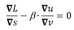
In this configuration, the effect of kinematic variables ”s”, ”u”, and ”v” on ”L” can be defined by
In this configuration, the effect of kinematic variables ”s”, ”u”, and ”v” on ”L” can be defined by
DRAFT: KINEMATICS OF SLIDING
Kinematics is a subfield of physics. In this article, we discuss the cases where individual entities slide against each other. Here, the ‘individual entities’ represent something distinguishable from its environment: solids—especially solids of revolution—fluids, and even vortices and porous solids. Examples include tyres, gears, cams, shafts, grinding wheels, but also a whirlpool or a galaxy.
Such situation affects both contacting surfaces to some degree, depending on a whole range of factors. From a kinematic point of view, a factor termed ‘sliding distance’ can be defined as the total path length traveled by an imaginary point on a sliding surface as it moves against a counterface (see visualization).
In the simple case of a blue prism sliding smoothly along a fixed plate a kinematic analysis reveals the difference in sliding distances for each body. An imaginary point on the blue prism’s contact surface travels the full sliding distance, L. In contrast, a point on the yellow-shaded counterface has a sliding distance of a.
This holds true assuming both the blue prism and the plate are perfectly rigid, maintain ideal contact, and the plate remains static.
In reality, both entities experience changes that affect the surface zone to a certain depth during sliding. For example, the counterface can also move during the sliding event and while maintaining contact, whether due to motion of the entire plate or due to its elastoplastic deformation.
A longer sliding distance increases the duration of contact, creating more space for phenomena like chemical reactions, heat transfer, abrasive wear, or some other mode of interaction (such as electromagnetic engagement or information exchange). A general equation showing the multidimensional dependence of those kinetic variables can be formulated as follows:

While L ultimately becomes a scalar measure (L = total sliding distance), its evolution is governed by changes occurring across multiple additional dimensions—including but not limited to wear, pressure, temperature, material properties, surface roughness, lubrication conditions, and thermal effects.
This constraint equation describes how sliding distance L emerges from the complex interplay of multiple factors:
- ∇L/∇s: How L responds to contact geometry changes across all relevant dimensions; s = contact length
- ∇u/∇v: How velocity fields couple across the multidimensional parameter space; u = sliding velocity; v = velocity of the entity for which we calculate L
- β: Modulates how strongly velocity variations influence the process relative to geometric variations.
The equation acknowledges that we cannot isolate the effect of an individual factor—all dimensions influencing s, u, and v collectively determine the resulting sliding distance L. The nabla operator ∇ represents multidimensional derivatives—the combined effect of other (hidden) variables.
Regardless of what other physical and chemical phenomena are at play, their collective effect on L satisfies this kinetic gradient relationship. This makes the equation useful for complex systems where multiple factors influence the outcome, highlighting the need to isolate or measure each of them individually.
At the kinematic level, the partial-derivative formulation still accommodates many real-world cases.

The above partial-derivative equation holds at the specific values of the variables where the derivatives are evaluated, with all other variables held fixed. As contact advances, the extra sliding per unit path depends on the sensitivity of the relative speed to the body’s speed. The constant C is a simple scale factor that converts this speed sensitivity into sliding distance for the specific setup. It can fold in geometry and operating details. For example, for a rotating body in sliding contact, C can represent the number of revolutions.
The following case illustrates the application of the kinematic model introduced above. The so-called twin-disc setup is widely used to investigate the wear resistance of materials across a broad range of engineering systems (Fig. 1).

Discs A and B, held in contact by a normal load, rotate at different angular velocities. In this configuration, the effect of kinematic variables s, u, and v on L can be defined by